Note these instructions cover the Skiffy 642 but the process is very similar for all the double row Skiffy’s (642, 656, etc.).
The Skiffy is a laser cut wood or acrylic enclosure with various 3D printed parts and fasteners. There are many ways to assemble it, though I find it’s best to work bottom up.
A couple of notes before we begin. The birch option tends to fit a little looser than MDF. In both cases if you find things aren’t coming together, be sure things are not at an angle or there isn’t some obstruction. If all looks well, you can firmly press on the finger joints or even lightly hit them with your first. If you are planning on getting out a Device of Convincing (a hammer) then something is probably wrong so double check! For acrylic cases, note that the acrylic may come with the backing plastic still applied, usually on one side. Be sure to peel it off before assembly.
Second, there is usually a “good side” and a “bad side” for the sides. I recommend facing the bad side inwards.
Third, sometimes one of the holes on the inside tabs can be a little hard to screw into. This is due to how the part is printed. It’s normal but if you find it’s difficult, run the screw through the hole first to loosen it up and then apply the nut.
With that out of the way, let’s go!
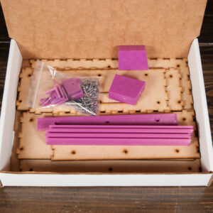
First, let’s lay out all the parts.
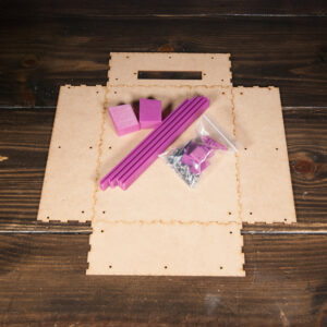
The parts are as follows:
- 1 Allen Key
- 22 Round Nuts
- 28 12mm Hex Flange Bolts
- 54 Square Nuts (6 for the backside of the rails, 12 for the front of each rail)
- 4 Sticky Feet
The 4HP power/accessory option then adds:
- 2 12mm Non-Flanged Bolts
- 2 Round Nuts
The rails on your Skiffy may already come with some or all of the nuts pre-loaded.
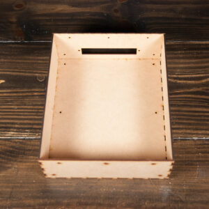
Building the Box
First, I find it easier to assemble the box together itself. With MDF it usually can hold together itself. Hardwoods might make things a bit loose where you want to use the tabs to assemble it as you go.
Right off the bat you need to make a decision for if you want to use the included stands, which tilt and angle the Skiffy a bit, or if you want it to sit flat. These instructions assume you will be installing the feet, but either way, the first step is to install the corner tabs onto the bottom.
Installing the corner tabs and optional feet
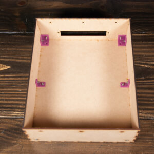
At this point you can install the corner tabs to attach the sides together. You will use the hex flange bolts and rounded nuts. If you plan on installing the feet, you can skip screwing the base to the corner tabs and instead install the side tabs which connect the sides to the bottom. That makes things rigid enough to then work on the feet.
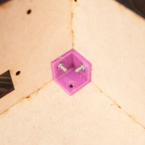
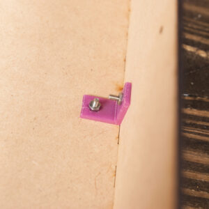
As noted earlier, you may find one of the holes is a little tight. This has to do with how the part is printed. Generally this is a non-issue but can make initial assembly a little difficult. Run a screw through the side of the tab you plan on placing against the bottom first to make sure it runs through without issue.
If you are using the feet, the taller feet go on the back. Run a screw through a foot and then up and through the base and into the tab. Then place a nut on the other end. I find it can be easier to screw the nut down a bit. This is especially true with the taller feet. Getting the allen key onto the bolt properly on the taller feet can take some fiddling about.
If you are working on a surface that can scratch easily, you may want to apply the adhesive feet right after. If you are not using the fit, you can place them anywhere on the bottom, but the circles on the corners are the recommended spots. If you are using the feet, place them on the flat part of the foot (do not cover the screw hole).
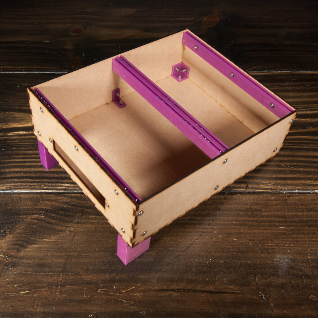
Installing the Rails
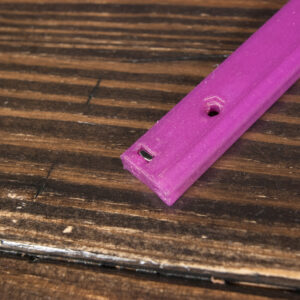
There are 3 rails, 2 are identical and are for the top and bottom and one for the center. If the rails do not yet have nuts along the front (where the modules will mount) go ahead and load them in. Note each rail has 2 square nuts along the back or tops which are used to mount the rails to the side of the case. Be sure to set aside 6 square nuts for these purposes.
If you’re having trouble installing the square nuts into a particular rail, try the opposite side. One side is often easier to load than the other.
You can install these in either order though I usually install the center one first. The center one is special since it has square holes along the rear rather than the top or bottom like the other 2 rails. To make things easy, install square bolts into the holes along the back of the center rail and then place the rail facing down (with the install square nuts facing upwards).
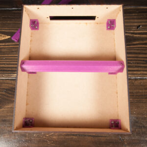
This allows you run 2 flanged screws through the sides and into the square nut without the nut falling out. Leave the rail loose. We will tighten it down after the other rails are install.
Next install the top and bottom rails. For these, the slots for the square nuts are along the top. I recommend mounting the rails with these slots pointed upward which prevents the nut from falling out when screwing it down. This means you can see the nut slot along the bottom rail if you don’t have it populated with modules or cover plates. If you find that unsightly, you can hide the nut hole but need to make sure it doesn’t fall out when screwing the rail to the case and may need to move the case around to do so.
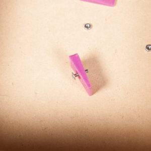
For the top and bottom rails, run bolts through the side first. Then add the center bolt and rounded nut to attach the rails to the top and bottom. You may need to hold the rounded nut in place while you start screwing a bolt through the case and into the rail. Do the same thing for the remaining bolts for both rails.
Now you can tighten everything down. Note the middle rail may still rotate a little. This is fine as it will become much more rigid once modules are mounted.
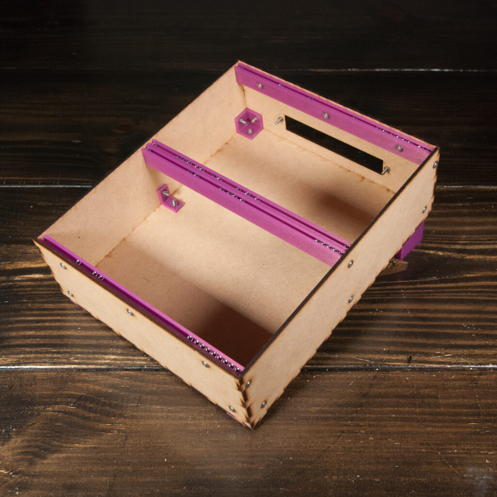
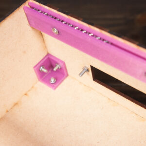
Installing a 4HP Module
The 4HP cutout was originally designed for 4HP power options (I personally tested a uZeus) but nearly any 4HP module could be mounted as well as an I/O plate, or even just vents. It’s up to you! These instructions assume a power module will be used.
There are two methods of mounting it.
The first is the “Normal” way where you just place the module through the hole and screw it down using the included non-flared screws and nuts.
The inside method can be used if your module is not fitting well through the cutout or you just prefer the look. Note that the inside option is a bit less rigid.
Adding Anti-Slip Stickers
If you are using the feet, add the stickers to the flat part of each foot (do not cover the screw hole). If you prefer to use the case flat and are not using the feet, add them to the corners along the bottom of the box. You can place them next to the bottom screws (do not place them on top).
And that’s it! You’re ready to throw some modules in it and start making music! If you have any questions please don’t hesitate to reach out!